
Alright, the groundwork is perfect, the secondary containment system is in place, and it’s time to install the primary barrier—the RPE geomembrane itself. This is where the big-picture design meets the critical details that make or break the installation.
In this chapter, we’ll cover the keys to getting those details right. These are the essential engineering decisions you face at this stage: developing an efficient panel layout, specifying the anchor trench to secure the entire system, and detailing the penetrations for pipes and structures. Nail these elements on the drawing board, and your field crew will have the best possible chance for a smooth, successful installation.
Panel Layout Strategy: Let the Experts Handle It
Turning a set of complex reservoir drawings into an efficient, buildable liner plan is an art form. It requires specialized software and a deep understanding of how massive RPE panels are fabricated, folded, shipped, and deployed. Your best bet here is simple: partner with an experienced RPE fabricator.
Provide them with your final, approved grading plan (usually in CAD format). Their technical team will analyze the reservoir’s exact geometry—slopes, corners, sumps, and penetrations—to create a detailed panel layout drawing. The goal is always the same: maximize panel size, minimize material waste, and orient the panels to minimize the number and complexity of field seams. They’ll figure out the most efficient way to weld the raw material in the factory to create these optimized panels.
The result is a system delivered to your site with:
- Clearly labeled, accordion-folded or rolled panels.
- A precise “map” showing exactly where each panel goes and how it connects to the next.
- Expert support available to answer any questions your installation crew might have.
The support of an expert fabricator transforms what could be a logistical nightmare into a straightforward assembly process.
The “Lost at Sea” Alternative
You could try to manage this task yourself, ordering bulk rolls of liner and tasking your field crew with figuring out the layout on the fly. (Hint: Don’t do it!) You’ll inevitably end up with far more material waste and a dramatic increase in slow, expensive, and risky field seaming. This approach shifts the complex planning burden from factory experts onto a field crew juggling weather, schedules, and heavy equipment. Partnering with your fabricator on a custom layout is a critical risk-management step that saves time, reduces waste, and sets the stage for a higher-quality installation.
Specifying the Anchor Trench
The anchor trench is a simple but powerful feature that locks your entire multi-layer geosynthetic system—GCL, secondary liner, geonet, and primary RPE—into the surrounding earth. It’s essentially a ring-shaped deadman anchor for the whole setup.
Each individual element of the liner system extends up the slope, above the final water level. Here, the layers are pressed together as a sandwich into a trench dug a few feet back from the crest. Backfilling this trench with properly compacted soil creates a powerful mechanical lock.
This unified anchor ensures the system resists the immense gravitational forces pulling down the slope, preventing slippage or pullout for the life of the facility. Getting the specification right is essential, and that comes down to a straightforward geotechnical calculation: the resisting force provided by the backfill must significantly exceed the driving force exerted by the liner system, usually with a Factor of Safety of 1.5 or better.
This is where you bring in the geotech specialist. They’ll run the numbers based on key inputs like liner strength, slope geometry, backfill soil properties (unit weight and friction angle from the geotech report), and the weight of the cover load. Based on these variables, they’ll specify the required trench geometry (depth and width) to guarantee stability.
This guide focuses on the engineering principles for trench specification. For the nuts and bolts of the actual construction—digging the trench, placing the liner, and compacting the backfill—consult your fabricator’s installation guidelines and industry best practices.
Detailing for Penetrations and Structures
A flat, continuous liner is easy. The real test of a sound installation often comes down to how you handle the details—the pipes coming through, the places where the liner meets concrete, and the tricky folds at the corners. Get these wrong, and you’ve got a built-in weak point.
Pipe Penetrations: Boot ‘Em Up
Any pipe passing through the liner is a potential leak path. The most reliable solution is a factory-welded boot that completely encapsulates the penetration.
Prefabricated Boots
For standard, common pipe sizes, the easiest solution is a prefabricated boot. These are mass-produced, cone-shaped components made from the same RPE material as your liner. They are designed to slip over the pipe and feature a wide flange at the bottom that can be directly welded to the main liner sheet, creating a seamless, watertight seal.
Custom Boots
Most PSH projects involve non-standard infrastructure. For very large-diameter pipes, rectangular structures, or penetrations at unusual angles, an experienced fabricator can design and build custom boots. This provides the same high-reliability, factory-welded quality as a prefab boot, but it’s tailored perfectly to your project’s specific geometry, eliminating the guesswork and risk of complex field wrapping.
Field Wrapping
If a factory-made boot isn’t feasible for some reason, the alternative is field wrapping. This involves a highly skilled technician carefully cutting and welding multiple pieces of RPE material around the penetration and onto the main liner. It’s a labor-intensive, more operator-dependent process, but it can achieve a reliable seal when performed correctly.
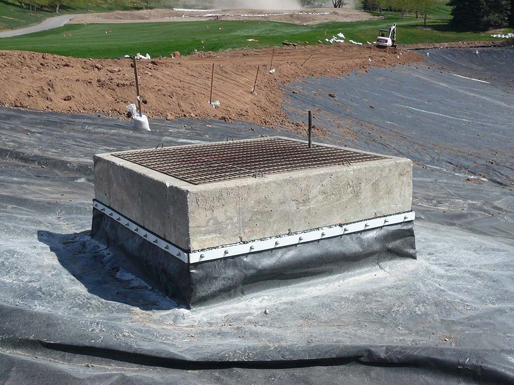
Concrete Connections: Batten Down the Hatches
Where the liner meets a vertical concrete structure (like a spillway wall or intake tower), you need a robust mechanical seal. The standard method uses batten strips.
The System
The RPE liner is run up the concrete wall, and a continuous strip of stainless steel or aluminum (the batten strip) is placed over the liner. A bead of high-quality sealant is applied between the liner and the concrete. Then the batten strip is tightly bolted through the liner into the concrete using anchor bolts, compressing the sealant and creating a watertight seal. It’s a belt-and-suspenders approach: a chemical seal backed up by a mechanical one.
Corners: Avoid the Pinch
Corners are natural stress points in any liner system. The key is to fold and weld them to avoid sharp creases or “pinch points” where the material could be strained.
- For an inside corner (like the bottom corner where the slope meets the floor), the standard technique is a simple “bathtub fold.” The excess material is neatly folded flat against one of the surfaces, creating a smooth transition without any sharp folds.
- Outside corners require a bit more finesse, such as a specific pattern of cuts and welds to create a tailored fit that lies flat against both surfaces without stretching or bridging the corner.
For both pipe boots and corner details, your fabricator or an experienced installation crew will have standard, proven methods. Rely on their expertise for these critical details.

